 All projects
September 2026· Shelved, fully documented
Canard-Guided Rocket
A senior capstone designed to steer a rocket with its own fins — and the CFD run that ended it.
- GNC
- Control Systems
- CFD
- SU2
- Fusion 360
- KiCad
- Python
- OpenRocket
- RocketPy
Most rockets fly where you point them. This one was supposed to decide where it was going after it left the rail — launched almost flat, at about 30° of elevation, then rolling to put its lift where it wanted it and holding the bank while the turn ran. Four forward canards, each on its own servo, doing the steering.
The frozen design turns at 9.76°/s, which works out to an 893 m radius, 2.6 lateral g, and roughly 65° of total heading change across the ~16 seconds it has the dynamic pressure to do anything at all. That is the number the whole project was pointed at, and getting it out of a hobby motor and four model-aircraft servos was the entire exercise.
It is also a project I stopped. The short version is at the bottom; the reason is in the CFD.
The vehicle
79.4 mm fiberglass airframe, 1365 mm nose to tail, on a Cesaroni J401FJ — 1105 N·s, a class J motor, which means it needs a Level 2 certification to fly. 6.71 kg wet, 6.20 kg dry, 972 m apogee, Mach 0.412 at the top. Static margin runs 2.07 to 2.45 calibers.
The thing worth knowing about a canard vehicle is that the control surfaces are expensive. Lift up front, ahead of the center of gravity, is destabilizing by definition — the same airframe with the canards deleted sits at 4.74 calibers of margin. The canards cost 2.28 calibers, and that is the price of being able to steer at all. It's also why you can't simply make them bigger when you want more authority: past a point they stop being control surfaces and start being the reason the rocket tumbles.
Both fin sets were sized together, by a Monte Carlo on margin robustness rather than independently against nominal stability. Canards and aft fins pull margin in opposite directions, so trading one against the other in sequence lands somewhere worse than searching them jointly under a probabilistic constraint.
The mechanism
The airframe diameter was never an aerodynamic decision. It was set by what had to fit inside it: four servos, their horns, four hinge shafts and the bearings those shafts run in, all in the same 143 mm module, all clear of each other at full deflection.
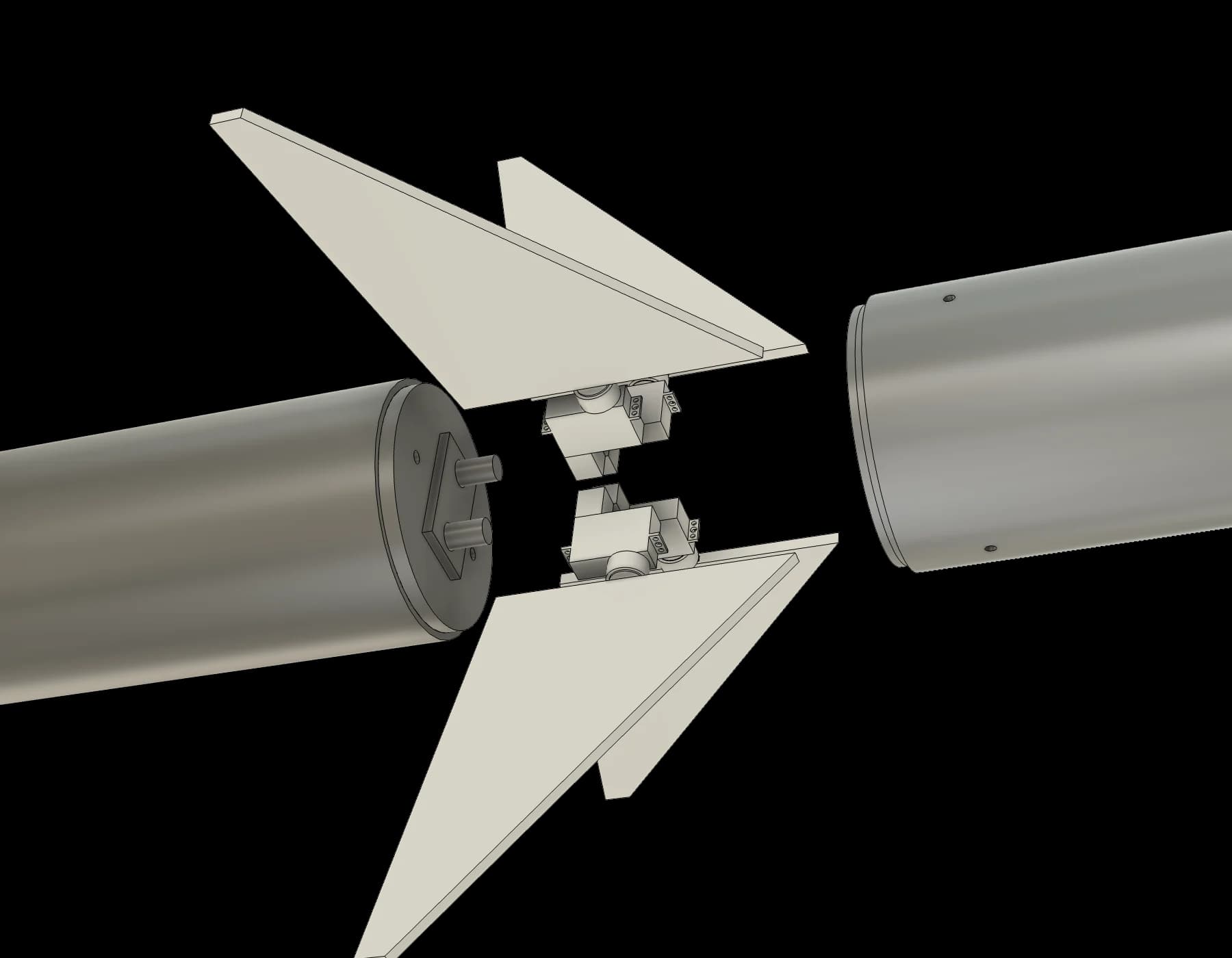
Every one of those parts is a link in a load path that starts at the panel and ends in the airframe wall: panel, root tang, shaft, spline coupling, bearing, bearing seat, and the tube section that has a 12 mm hole cut through it four times at the same station. The CAD is a full Fusion model, nose to tail, including the motor mount and the recovery hardware, and each joint in that chain has its own margin computed against the hinge moment rather than assumed.
The flight computer
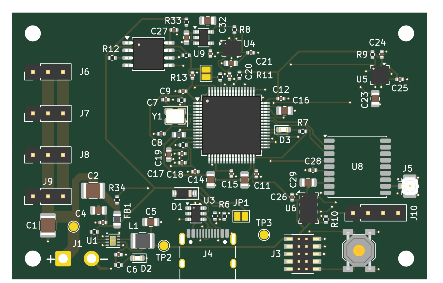
A four-layer board in KiCad — 767 tracks, 147 vias, 85 footprints, 101 nets, 2.33 mm stackup, DRC clean, with a fab package ready to send. It is a custom board rather than a commercial altimeter because nothing off the shelf runs a control loop; the ejection charges stay on an independent commercial altimeter, deliberately, so that a bug in my guidance code cannot take the parachute with it.
Three things turned up while specifying it that two previous design documents had both missed: a gyro full-scale requirement no purchasable part actually satisfies, a power budget that had never been written at all, and a logging requirement that had never been converted into bytes per second. Two of them changed a part.
Then the CFD disagreed
The design tool is my own — Barrowman stability buildup, component drag, hinge moments, trajectory integration, a sizing sweep over 100+ real motor thrust curves — and it was cross-checked against OpenRocket and RocketPy the whole way. The last thing I did was run the actual geometry through SU2, an inviscid Euler solve at Mach 0.45 on a 1.85 million cell mesh, plus my own vortex-lattice code as a second opinion.
The first thing it did was confirm the airframe. SU2 put the center of pressure at 980 mm against my tool's 975 mm — 0.06 calibers apart, from a method that shares no theory whatsoever with Barrowman. That is a better agreement than the OpenRocket cross-check, and it means the stability margin the whole vehicle is built around survived a genuinely independent check.
The second thing it did was contradict two assumptions the hardware had already been sized on.
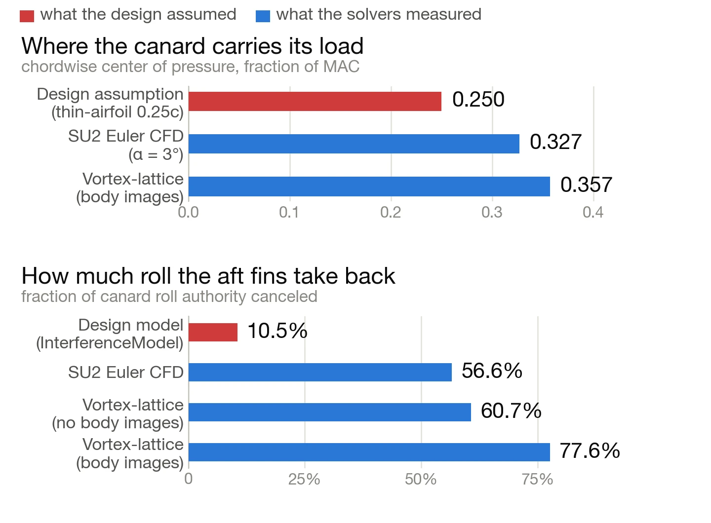
The canard carries its load further aft than I'd assumed. My hinge moment code used
cp_frac = 0.25 — the thin-airfoil quarter-chord value, a constant that had been in the file from
the start and was never computed for this particular planform. SU2 puts it at 0.327 of the mean
aerodynamic chord; the vortex-lattice code says 0.357. A 10:1-taper, 42°-swept delta simply doesn't
behave like thin-airfoil theory. That moves the moment arm about the hinge from 2.98 mm to between
7.6 and 9.4 mm, and it takes a servo torque margin reported as a comfortable 2.03× down to
0.73× — meaning the servo cannot hold the canard against the airstream at full deflection and
maximum dynamic pressure. The one number the entire actuator selection rested on.
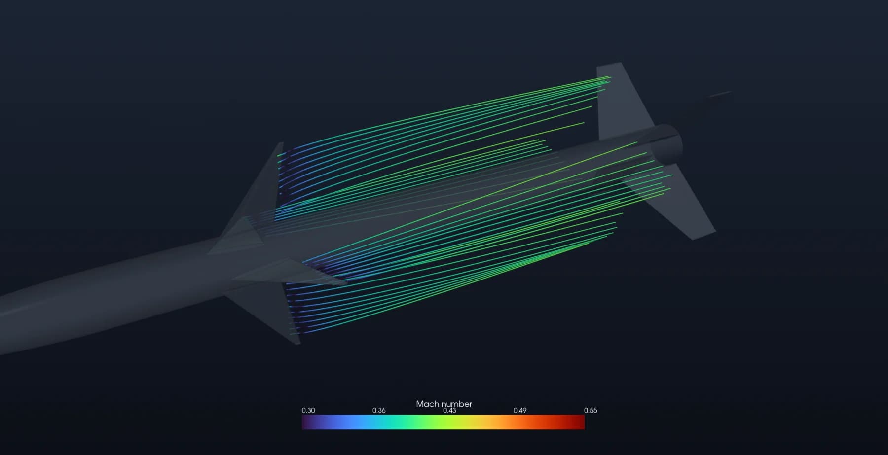
And the aft fins eat far more roll authority than I'd modeled. The interference model had them cancelling 10.5% of what the canards command. SU2 says 56.6%. The vortex-lattice run says 60.7% without body images and 77.6% with them. The mechanism is visible in the render above — the wake each canard sheds lands on a fin that is 45° away and most of a meter downstream, and that fin generates its own roll in the opposite direction.
Why I stopped
Both findings are fixable. Neither fix is software.
The hinge station is what sets the shaft, the collars, the servo positions and the bores through the airframe wall, so moving it is a rebuild of the canard module in CAD, followed by a converged mesh to check the new numbers, a servo bench test to measure the lag the datasheet doesn't publish, and ultimately flight data to replace the interference factors with measured ones. That is months of mechanical work before a single line of guidance code gets any better.
I'm a CS student, and the part of this I care about is the estimation and control software — not another revision of a servo bay. So I stopped at the point where the design is honest about its own numbers rather than at the point where it looks finished. The tool now prints the CFD-informed 0.73× FAIL right next to the 2.03× it used to report on its own, because a sizing tool that quietly keeps reporting the comfortable number is worse than no tool.
Everything is reproducible: the aero derivations, the CAD, the board, the CFD cases, and a handoff document listing every open item I did not close.
The Level 2 certification this vehicle needs is the next rung up from the High-Power Rocket that earned my Level 1.